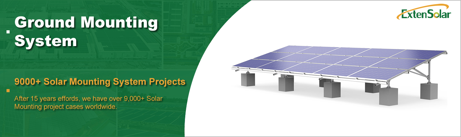
Details
| Surface Treatment |
Anodized |
Material |
Aluminum Alloy 6005-T5 |
| Place of Origin |
China |
Installation Site |
Open Field |
| Brand Name |
Exten |
Model Number |
A02-1 |
| Standard |
|
Certificate |
AS/NZS1170.2/CE/ISO |
| Wind Load |
60m/s(196.85ft/s) |
Module Orientation |
Landscape Portrait |
| Wind speed |
Yo 60m/s |
Max Snow Load |
1.4KN/m2 |
| Snow Load |
1.4KN/m2(29.24psf) |
Service Life |
25YRS |
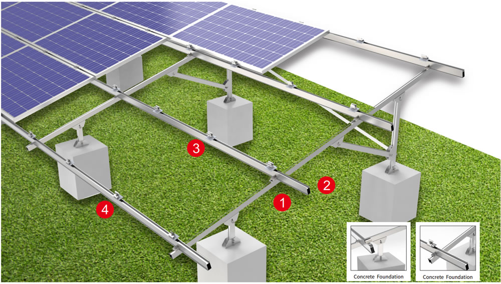
Component List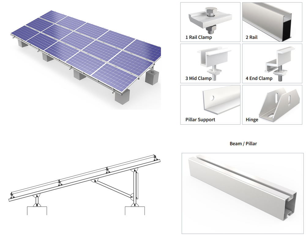
| Description |
Material |
Specificatioin |
Quantity |
| Beam |
Q235B |
4200mm |
5 |
| Purlin |
Q235B |
7100mm |
4 |
| Column suppirt 01 |
Q235B |
1700mm |
4 |
| Column suppirt 02 |
Q235B |
2000mm |
4 |
| Beam suppirt 01 |
Q235B |
1735mm |
5 |
| Beam suppirt 02 |
Q235B |
1880mm |
5 |
| Column 01 |
Q235B |
852mm |
5 |
| Column 02 |
Q235B |
2005mm |
5 |
| Hinge connector |
Q235B |
|
30 |
| Column base |
Q235B |
|
10 |
| Mid Clamp |
AL 6005-T5 |
50mm |
20 |
| End Clamp |
AL 6005-T5 |
50mm |
8 |
| U Bolt |
Q235B |
mm |
10 |
Advantages
Simple structure—no piles or grouting required; stability is achieved solely through the concrete’s own weight. Ready to install upon arrival; deployment can be completed with a forklift and manual labor, resulting in a short construction period.
High adaptability.
Slight unevenness in the ground can be leveled using shims. Upon project completion, the foundation can be hoisted away directly, leaving no trace on the site.
Wind resistance is ensured through precise counterweight calculations; each foundation is verified for overturning moments, and stability is guaranteed once the load-bearing capacity meets standards.
Low maintenance costs. Since all components are above ground, inspections are straightforward, and loose bolts or foundation displacement can be detected at any time. Issues such as underground corrosion and frost heave associated with ground-anchored supports simply do not exist here.
Summary: Quick installation, quick relocation, and quick maintenance—solving on-site problems using the most straightforward physical principles.
Installation
1. Level and compact the ground, ensuring the slope does not exceed 2 degrees. When surveying and staking out the site, use a total station to mark the position of each foundation point, keeping the error within 5 millimeters. If the subgrade is too soft, you must replace the soil; don’t try to cut corners—settlement later on will cause you even more headaches.
2. Hoist the concrete foundation blocks into place. Immediately after positioning, use a level to ensure the height difference in all four directions does not exceed 3 millimeters. Pack thin steel shims tightly around the base to ensure it sits firmly in place without wobbling or shifting.
3.Begin installing the columns from both ends. Stretch a guide line, and align the middle columns along this line; the entire row will naturally be straight. Tighten the bolts in three diagonal stages, applying torque according to the drawings. Leave a 10-millimeter gap at the main beam joints to allow for thermal expansion and contraction—this detail is crucial.
4.Finally, install the panels. Start from either side and use clamps to hold them in place temporarily—do not lock them down completely. Once all panels are aligned and the gaps between them are uniform, tighten all bolts simultaneously. After completion, use a torque wrench to spot-check 5% of the connection points to ensure they meet specifications. Take care to protect the panel surfaces throughout the process; do not leave tools lying around to avoid scratches or hidden cracks. Clean up the work area thoroughly when finished.
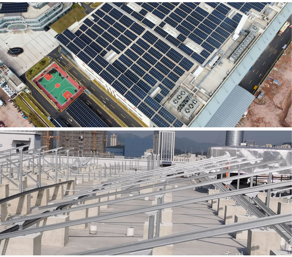
Case
FAQ
1. What types of site conditions are suitable for this mounting system?
Self-supporting mounting systems do not rely on piles; instead, they stabilize the structure solely through the weight of concrete blocks, so there are strict requirements for the foundation’s bearing capacity. The ideal site consists of hard soil with uniform compaction or a gravel surface, with a slope preferably kept within 2%. If the subgrade is too soft, the backfill is too thick, or the water table is too high, the foundation is prone to uneven settlement, which can cause the mounting system to deform and the modules to develop hidden cracks. A subgrade bearing capacity test must be conducted before installation begins; if the results do not meet standards, the backfill must be replaced or the foundation reinforced—do not take any chances.
2. How wind-resistant is the system? What wind force level can it withstand?
Wind resistance depends entirely on the coordination between the foundation ballast and the support structure design. We calculate based on the local 50-year return period basic wind pressure; the foundation weight has been rigorously verified to be sufficient to resist uplift forces and overturning moments. During on-site installation, foundation blocks must be positioned correctly with tight contact surfaces and must not be left suspended. In actual projects, properly designed self-weighted support structures can withstand typhoons of Category 12 or higher—provided that the foundation dimensions and quantity are not compromised, and each foundation is compacted during installation.
3. What is the most critical step during installation?
Leveling. Many people think that simply placing the foundation in position is sufficient, but in reality, the levelness of the foundation’s top surface determines the stress distribution of the entire support structure. If the height difference exceeds 3 millimeters, the columns will tilt, causing the array layout to become misaligned and placing undue stress on the connectors. Under long-term loading, this significantly increases the risk of bolt loosening and weld cracking. Therefore, after the foundations are hoisted into place, each one must be checked individually with a level, and fine-tuned using thin steel shims. Taking a little extra time on this step ensures everything goes smoothly afterward.
4. Can the foundations be reused?
Yes. This is a distinct advantage of self-supporting racks. The concrete foundation blocks are independent components that are not embedded underground; when relocating or expanding a project, they can be lifted and moved directly. During disassembly, take care to protect the embedded bolts and avoid damaging the edges. After removal, the site is left virtually untouched—there is no need to break up the ground or perform extensive restoration work. This feature is particularly practical for temporary projects or projects on leased land.
5. What should be noted regarding daily operation and maintenance?
Daily maintenance is minimal, but there are a few things to keep an eye on. First, inspect the ground around the foundation every six months for any potholes caused by rainwater erosion. If any are found, backfill them promptly to prevent the foundation from becoming suspended. Second, randomly check the torque of the connecting bolts—especially before and after high-wind seasons—and retighten them if they’re loose. Third, check the module surfaces for any abnormal misalignment. If you notice an entire row of racks tilting, immediately recheck the level and identify the cause. Most problems are easy to resolve if caught early; if left unaddressed for too long, they’ll require major repairs.


