Details
| Surface Treatment |
Anodized |
Material |
Aluminum Alloy 6005-T5 |
| Place of Origin |
China |
Installation Site |
Open Field |
| Brand Name |
Exten |
Model Number |
A02-1 |
| Standard |
|
Certificate |
AS/NZS1170.2/CE/ISO |
| Wind Load |
60m/s(196.85ft/s) |
Module Orientation |
Landscape Portrait |
| Wind speed |
Yo 60m/s |
Max Snow Load |
1.4KN/m2 |
| Snow Load |
1.4KN/m2(29.24psf) |
Service Life |
25YRS |
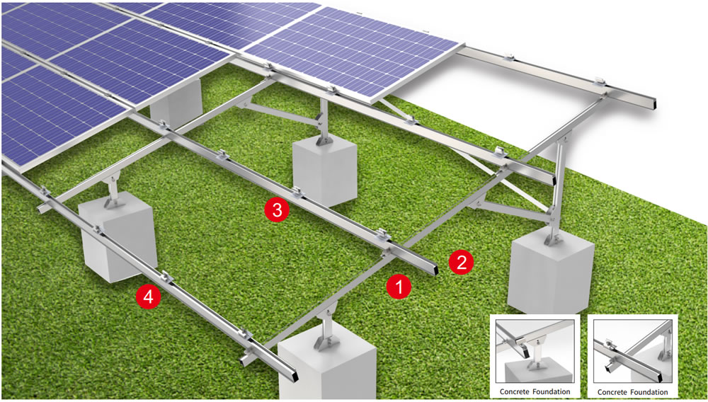
Component List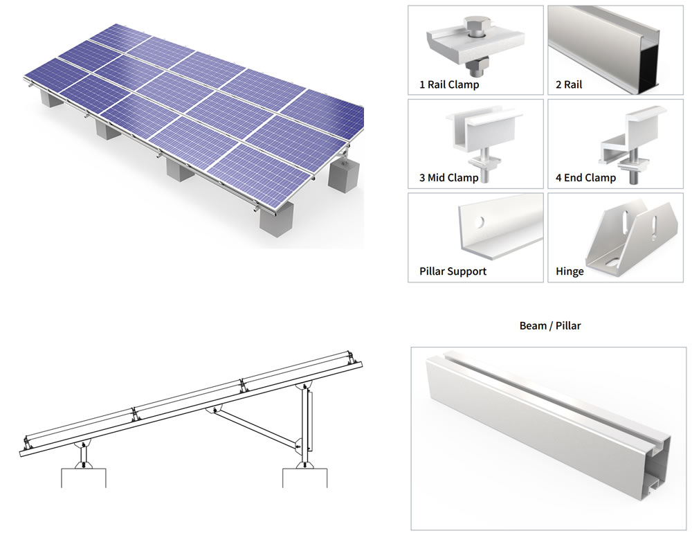
| Description |
Material |
Specificatioin |
Quantity |
| Beam |
Q235B |
4200mm |
5 |
| Purlin |
Q235B |
7100mm |
4 |
| Column suppirt 01 |
Q235B |
1700mm |
4 |
| Column suppirt 02 |
Q235B |
2000mm |
4 |
| Beam suppirt 01 |
Q235B |
1735mm |
5 |
| Beam suppirt 02 |
Q235B |
1880mm |
5 |
| Column 01 |
Q235B |
852mm |
5 |
| Column 02 |
Q235B |
2005mm |
5 |
| Hinge connector |
Q235B |
|
30 |
| Column base |
Q235B |
|
10 |
| Mid Clamp |
AL 6005-T5 |
50mm |
20 |
| End Clamp |
AL 6005-T5 |
50mm |
8 |
| U Bolt |
Q235B |
mm |
10 |
Horizontal Panel Ballasted Ground Mount Solar System Advantages
This is a ballast system ground mount that does not require foundation work. The entire structure relies on its own weight and a horizontally arranged load-bearing frame to securely position the modules on the ground. The system features a wide counterweight base at the bottom, which uses gravity to resist wind pressure and lateral slippage without disturbing the existing soil layer. The horizontal layout lowers the overall center of gravity, making it suitable for areas with gentle slopes, soft soil, or ecologically sensitive regions. Both transportation and on-site assembly rely on bolted connections—no welding is required—allowing for rapid installation and easy relocation at any time. This makes it a practical solution for both temporary and permanent power plants.
First, it is land-friendly. With no piling or grouting required, there is virtually no disturbance to the ground surface. During reclamation, the support structure simply needs to be removed by crane, and the ground immediately returns to its original state, making it particularly suitable for agricultural PV, grass-solar complementary projects, or landfill sites.
Second, construction is extremely simple. All components are prefabricated in the factory; on-site installation requires only a standard wrench and a level, with no need for large-scale piling equipment or reliance on concrete curing times. A standard array can typically be installed from unloading to final positioning within half a day.
Third, reliable wind resistance. The horizontal design keeps the module tilt angle fixed and lowers the center of gravity. The counterweights have been optimized through wind tunnel testing; in areas with basic wind speeds below 35 meters per second, the safety factors for slip resistance and overturn resistance both exceed 1.5.
Fourth, flexible adjustment. The support beams feature multiple mounting holes, accommodating different module sizes and tilt angle adjustments ranging from 10° to 25°, making it easy to optimize power generation based on latitude or season.
Fifth, controllable costs. Although steel consumption is slightly higher than that of conventional pile-driven mounting systems, this solution eliminates the need for geological surveys, pile foundation testing, equipment rental, and backfilling costs. As a result, the total construction cost for small- and medium-sized projects is often comparable or even lower, and the construction period is shortened by approximately 40%.
Sixth, easy relocation. When expanding the power plant or repurposing the land, the entire system can be dismantled and reused, resulting in a high residual value recovery rate and avoiding long-term environmental liabilities caused by underground debris.
Solar Power Ground Mounted Installation
Step 1: Site preparation. Remove large rocks and protruding vegetation, and mark the array positioning lines using a laser rangefinder.
Step 2: Place the counterweight bases. Hoist concrete blocks or steel boxes to the marked points according to the spacing specified in the drawings, keeping the horizontal deviation within 10 millimeters.
Step 3: Assemble the crossbeam framework. On the ground, pre-tighten the longitudinal main beams and transverse connecting rods with bolts to form a grid-like plane, then hoist the entire structure onto the bases.
Step 4: Calibrate the elevation. Use a leveling instrument to adjust the shims at each support point, ensuring the framework’s flatness error is ≤5 millimeters.
Step 5: Install the components. Snap the photovoltaic panels into the rails on the crossbeams one by one, secure them with clamps, and tighten all bolts to the specified torque.
Step 6: Electrical wiring. Run DC cables through the cable trays along the sides of the mounting structure, connect them to the combiner box, and perform a ground continuity test upon completion. After the entire installation is finished, conduct a random wind resistance test—select two bases at random and use a tensile tester to verify that the slip resistance meets the design value. Once the acceptance inspection is passed, the system can be connected to the grid.
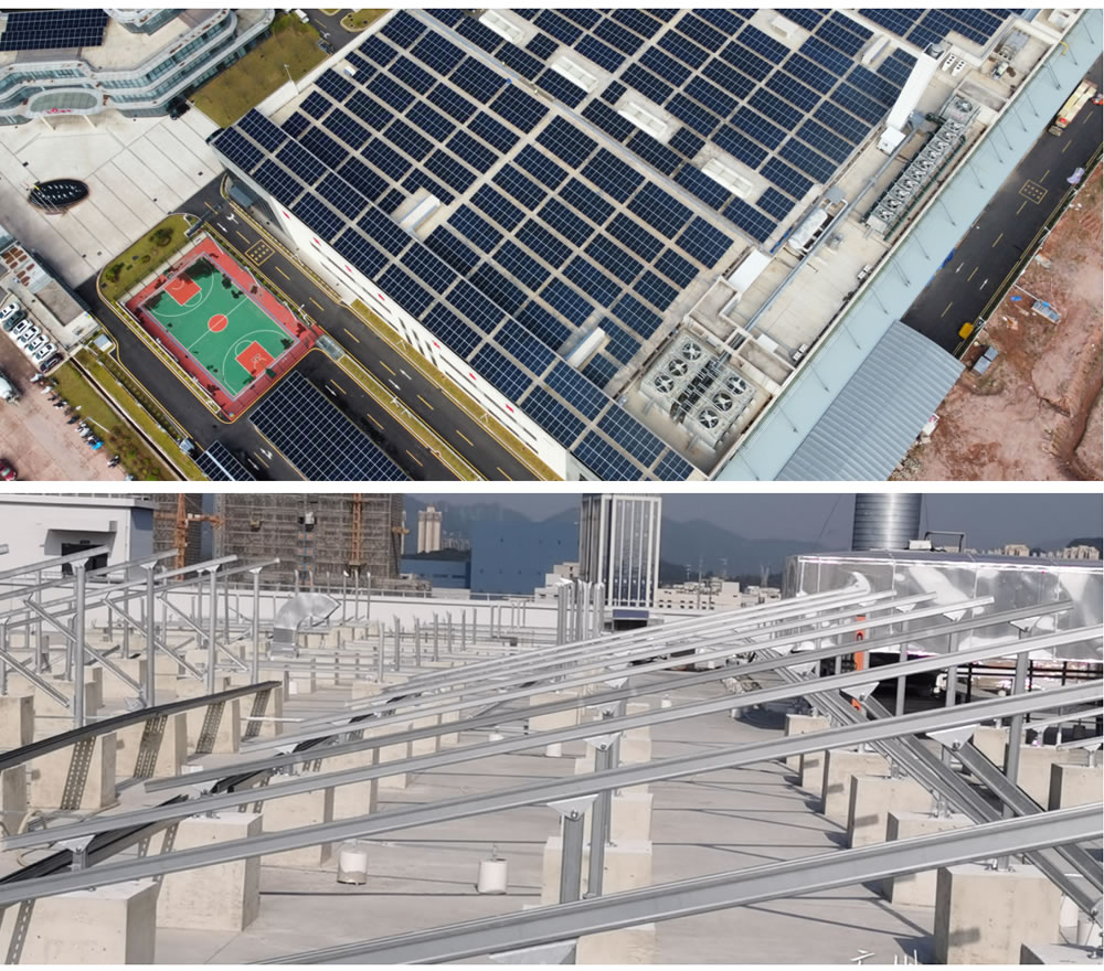
Ground Mounted PV Panels Case
FAQ
Q: Does the ground have to be completely level?
A: No. A forward-to-backward slope of no more than 5° and a left-to-right elevation difference of no more than 3° are permitted. If these limits are exceeded, steel leveling shims can be added without the need for additional earthwork.
Q: What materials are used for the counterweights?
A: Precast concrete blocks or steel boxes filled with sand and gravel are commonly used. Each block weighs between 200 and 500 kilograms; the quantity and layout are determined on-site based on the wind pressure calculation report.
Q: Are the modules easy to clean and maintain?
A: Yes. The mounting brackets are approximately 0.5–1.0 meters above the ground, allowing personnel to bend down and access the underside; there is ample working space for a pressure washer and maintenance tools.
Q: What should be done in the event of a heavy snowstorm?
A: The horizontal structure can withstand snow loads of up to 0.8 kN per square meter. If snow accumulation becomes too thick, the tilt angle can be manually increased to 25° to facilitate natural snow slide-off, eliminating the need for additional snow removal equipment.
Q: What is the service life?
A: The hot-dip galvanized coating on the main steel components is at least 85 micrometers thick, and stainless steel bolts are used for fasteners. In non-coastal, non-highly corrosive environments, the design life is 25 years, matching the lifespan of the modules.


