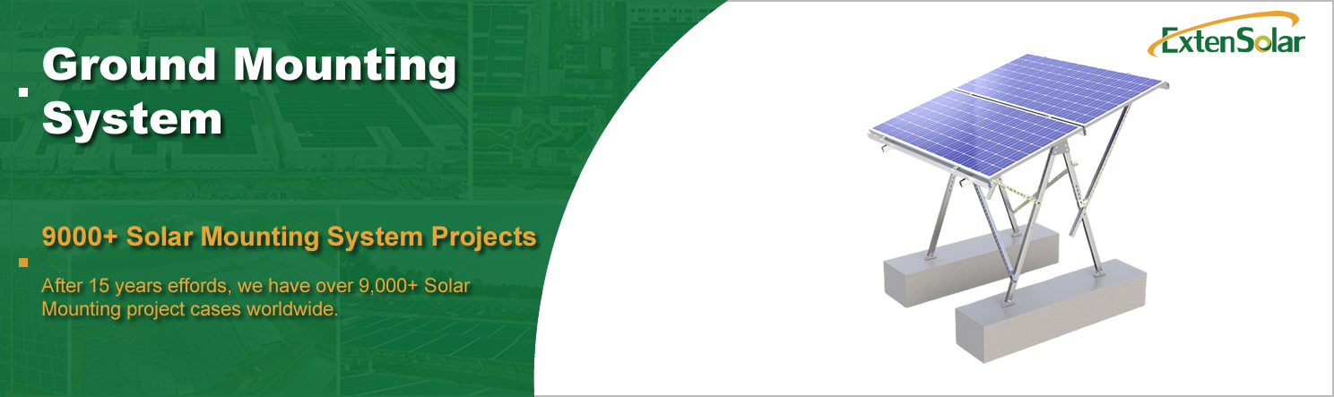
Adjustable Solar Ground Mount Details
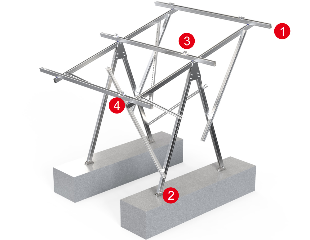
| Surface Treatment |
Anodized |
Material |
Aluminum Alloy 6005-T5 |
| Place of Origin |
China |
Installation Site |
Open Field |
| Brand Name |
Exten |
Model Number |
A02-1 |
| Standard |
|
Certificate |
AS/NZS1170.2/CE/ISO |
| Wind Load |
60m/s(196.85ft/s) |
Module Orientation |
Landscape Portrait |
| Wind speed |
Yo 60m/s |
Max Snow Load |
1.4KN/m2 |
| Snow Load |
1.4KN/m2(29.24psf) |
Service Life |
25YRS |
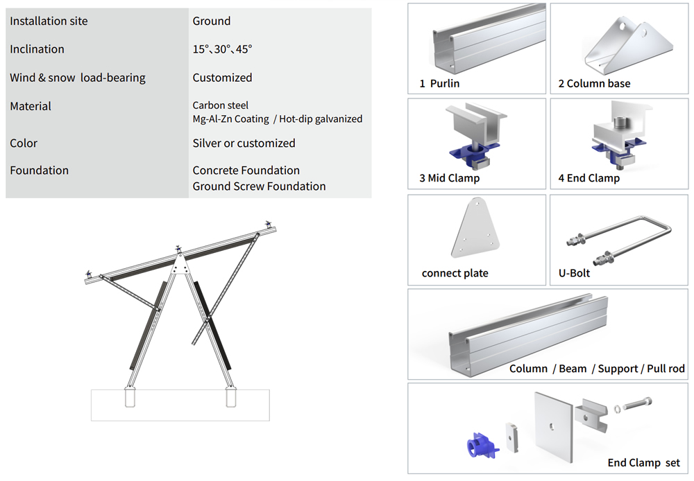
| Description |
Material |
Specificatioin |
Quantity |
| Beam |
Q235B |
2450mm |
2 |
| Purlin |
Q235B |
2278mm |
3 |
| Column suppirt |
Q235B |
2000mm |
2 |
| Beam pull rod |
Q235B |
2500mm |
1 |
| Beam suppirt |
Q235B |
878mm |
2 |
| Beam suppirt |
Q235B |
1645mm |
2 |
| Column |
Q235B |
1664mm |
4 |
| Triangle connect plate |
Q235B |
274mm |
4 |
| Column base |
Q235B |
150mm |
4 |
| Mid Clamp |
AL 6005-T5 & SUS 304 |
50mm |
2 |
| End Clamp |
AL 6005-T5 & SUS 304 |
50mm |
4 |
| U Bolt |
Carbon steel |
|
4 |
What is an adjustable solar ground mount?
This is a modular mounting structure used to secure photovoltaic modules to a ground foundation, allowing operators to manually or mechanically adjust the tilt angle of the modules. Unlike fixed-tilt mounts, its core value lies in adjusting the orientation of the panels in response to seasonal changes or the sun’s path, thereby optimizing the capture efficiency of incident solar radiation. The system typically includes posts, swivel bearings, telescoping support arms, and locking mechanisms, and is suitable for large, flat areas or slightly undulating terrain.
Why choose adjustable solar panel ground mount?
Because the sun’s trajectory throughout the year is not constant—it hangs low in winter and high in summer, with a difference in the angle of incidence exceeding 40 degrees between the two seasons. Once a fixed mount is welded to the ground, its tilt angle is locked in, forcing you to make a one-time trade-off between “maximizing power generation in winter” and “maximizing power generation in summer.” Whichever option you choose, solar radiation during the other season is wasted.
Adjustable mounts eliminate this trade-off. By adjusting the tilt angle 3 to 5 times per year according to the seasons, the modules are always positioned as close as possible to the optimal angle for sunlight, directly increasing annual power generation by 8% to 15%. This incremental gain requires no replacement of electrical equipment, adds no line losses, and occupies no additional land—it stems purely from the “sun-tracking dividend” achieved through mechanical adjustments. For ground-mounted power plants, the initial investment is only 12% to 18% higher than that of fixed mounts, while the payback period is extended by less than a year; the remaining two-plus decades consist entirely of net additional revenue. In high-latitude regions, cloudy climates, or projects with expensive land rents, this difference can even determine whether a power plant is worth building—it is not merely a nice-to-have feature, but a fundamental optimization measure at the structural level.
Adjustable Ground Mount Solar Rack Installation
1. Site Survey and Layout
Upon arrival at the site, first verify the geological survey data to confirm that the foundation bearing capacity aligns with the design parameters. Use an RTK surveying instrument to mark the center pile positions for each row of supports, keeping longitudinal and transverse deviations within ±10 millimeters. At the same time, grade the construction access road and clear surface debris to prepare for equipment transport and hoisting.
2. Foundation Construction
Select the foundation type based on the soil report. Helical piles are suitable for sandy soil or stiff-plastic clay and are driven directly to the design elevation using a hydraulic pile driver; concrete isolated foundations are used for weak soil layers or areas with high groundwater levels. These require excavation, reinforcing steel tying, formwork installation, and concrete pouring, and must be cured to at least 70% of the design strength before loading. The elevation error of each foundation top surface must not exceed ±3 millimeters.
3. Column and Rotating Main Shaft Installation
After the foundation has passed inspection, hoist the columns into place and use a laser level to calibrate verticality in both directions, with a tolerance of 2 millimeters. Next, install the rotating main shaft and its bearing housing assembly, tightening the connecting bolts in stages according to the torque specifications—initially to 50% of the specified value, and finally to 100%. During this step, check the diagonal dimensions to ensure the front-to-back parallelism of the entire row of structures.
4. Assembly of Adjustable Support Arms and Purlins
Connect the adjustable support arms to the pivot points on the main shaft and base, respectively, and apply weather-resistant grease to all rotating parts. Then install the transverse purlins and longitudinal braces to form a stable three-dimensional framework. At this stage, all pivot points are only pre-tightened—not locked—to reserve sufficient adjustment allowance for subsequent angle settings.
5. Module Installation and Electrical Grounding
Starting from the end of the array, install the photovoltaic modules one by one. Use a preset torque wrench to tighten the center clamps and edge clamps to 14–16 N·m to prevent hidden cracks in the solar cells caused by over-tightening. Simultaneously lay the DC cables and reliably connect the metal parts of the mounting structure to the grounding grid; the measured insulation resistance must exceed 2 megohms.
6. Angle Interlock Testing and Final Locking
Perform a no-load full-stroke operation: Adjust the tilt angle uniformly from the minimum design value (5°) to the maximum value (60°), then return it to the starting position; repeat this process for three complete cycles. Throughout the process, observe whether the movement at each hinge point is smooth and check for any abnormal friction noises or instances of out-of-sync movement. After passing the test, set the tilt angle according to the recommended angle for the current season, and lock all adjustment handles and lock nuts. Clean up the site and hand it over to the electrical commissioning team. For a 1.5-megawatt site under normal weather conditions, the total construction period is estimated to be 7 to 9 working days.
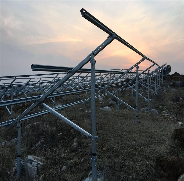
Case
FAQ
1: How long does a single adjustment take?
It depends on the system size and drive mechanism. For small arrays (≤50 kW), two workers using specialized wrenches can complete the entire tilt adjustment in about 20 minutes. For large power plants using electric actuators or hydraulic systems, a single adjustment can cover the entire site within one hour, without the need for large lifting equipment.
FAQ 2: Is a higher adjustment frequency always better?
No. Adjusting once a month yields minimal marginal gains (typically <1.5%), but increases labor costs and the risk of mechanical wear. The industry-recognized optimal strategy is to adjust 3–5 times per year—once each at the spring equinox, summer solstice, fall equinox, and winter solstice, with an additional fine-tuning at the end of winter in some regions. Excessive adjustments actually reduce net returns.
FAQ 3: Do adjustable mounts have any special requirements for the foundation?
Essentially none. The design loads for pile foundations or concrete foundations should be calculated based on wind pressure and snow loads at the maximum tilt angle. The adjustment mechanism itself does not alter the center of gravity by more than 5%, so no additional reinforcement is required. The only difference is that sufficient clearance must be provided for the moving parts; it is recommended to increase the spacing between adjacent arrays by 0.3–0.5 meters.
FAQ 4: Can the adjustment mechanism jam during severe weather?
High-quality products use galvanized steel and stainless steel pins, combined with sealed, lubricated bearings, and can withstand salt spray tests for over 1,000 hours. Regular inspections (twice a year) of the threads and grease condition can prevent rust and seizing. In the event of hail or severe dust storms, it is recommended to perform a light-load idle test after the extreme weather has passed, rather than shutting down the system immediately.
FAQ 5: How much longer is the payback period compared to fixed mounts?
The initial equipment cost is approximately 12%–18% higher, but the additional power generation revenue extends the payback period by only 6–10 months. Calculated over a 25-year lifecycle, the internal rate of return (IRR) for the adjustable solution is typically 2.3–3.1 percentage points higher than that of fixed mounts—making this a project decision with a very clear net present value.


